CCTV CAMERA POWER SUPPLY NOT WORKING DAHUA CAMERA ADMIN PASSWORD FORGOT DAHUA PASSWORD RESET BUTTON DAHUA DVR FACTORY RESET WITHOUT PASSWORD CCTV Camera Upgrade
In celebration of the upcoming Chinese New Year, our store will be closed from 9th to 12th February 2024.
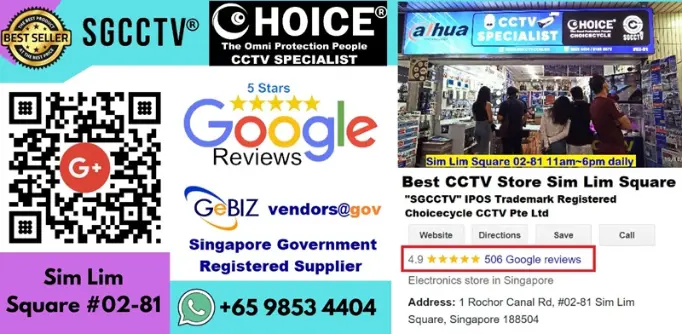
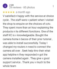
Specializing in CCTV camera access control security systems, we boast over 500 five-star Google reviews, placing us among the top-rated providers in this field.
Registered Trademark for SGCCTV in Singapore.Caution regarding misleading, misrepresented, or confusing pop-up and online stores, as well as potential scammers.
Good News for Local SME, there’s few grant, can help to defray the cost of our Security Systems. Whatsapp 98534404 for eligibility.
Fortify your success with our tailored security package CCTV systems, access control, software, installation with grant support.
CCTV CAMERA POWER SUPPLY NOT WORKING DAHUA CAMERA ADMIN PASSWORD FORGOT DAHUA PASSWORD RESET BUTTON DAHUA DVR FACTORY RESET WITHOUT PASSWORD CCTV Camera Upgrade
Join Our 20-Year Anniversary Celebration! Lucky Draw with Sure-Win Prizes: Dahua 4MP Pan & Tilt Camera, Hikvision 22″ Monitor, Ezviz Battery Camera & More! Everyone Wins a Prize! Exclusive Merchandise, Vouchers, Engaging Activities—Don’t Miss Out! Save the Date & Celebrate with Us